

Flexural capacity of beam-to-column joints with external diaphragm considering the slab effect
-
摘要: 樓板的存在對梁柱節點的局部受力影響顯著, 在梁柱節點設計中, 若僅僅把樓板與鋼梁的組合效應作為安全儲備, 可能會產生結構由"強柱弱梁"轉變成"強梁弱柱"的顛覆性結果, 因此忽略混凝土樓板對節點承載力及剛度的影響是造成破壞的重要原因.基于已完成的帶樓板的T型梁柱節點低周往復荷載試驗, 建立了非線性有限元分析模型.為了更加全面地了解鋼梁-樓板組合節點的工作機制, 進一步補充完善試驗研究的不足, 模型考慮了樓板與鋼梁之間的栓釘連接以及材料非線性等因素, 模型的計算結果與試驗結果具有高吻合度.在此基礎上, 通過有限元參數分析, 詳細分析了構件尺寸效應、軸壓比、樓板厚度、樓板強度和柱寬厚比共五個參數對考慮樓板影響的外環板式梁柱節點抗震性能的影響.結果表明尺寸效應、軸壓比對梁端抗彎承載力及剛度的影響小到可以忽略, 樓板厚度、樓板強度和柱寬厚比對梁端抗彎承載力有顯著影響.結合理論分析進一步提出了考慮樓板影響的外環板式梁柱節點梁端抗彎承載力計算公式, 通過對比公式計算結果與試驗、有限元分析結果可得, 該計算公式可較好的計算帶樓板外環板式梁柱節點梁端抗彎承載力.Abstract: The existence of concrete slab has significant influence on the local mechanical characteristic of the beam-to-column joint. In the design of beam-to-column joints, if the composite effects of steel beam and concrete slab are considered particularly as safety stock, the counteractive result of "strong column and weak beam" or "strong beam and weak column" may be produced; therefore, ignoring the influence of concrete slab affect the bearing capacity and stiffness of the joints. Based on the results of a full-scale cyclic test conducted on T-shaped beam-to-column joints, a detailed nonlinear finite element model was proposed. To completely understand the working mechanism of composite joints and further improve the experimental research, the nonlinear material properties and the shear effect of the connectors between concrete slab and steel beam were considered in the model. The results from the model agree well with the test results. Moreover, an extensive parametric study was performed to examine the seismic behavior of the joints. Parameters, such as the size effect, axial-load ratio, slab thickness, concrete compressive strength, and diameter-to-thickness ratio of the column, were investigated. The results show that the size and axial-load ratio have insignificant effect on the flexural capacity and stiffness of beam end, whereas the slab thickness, concrete compressive strength and diameter-to-thickness ratio of the column have significant effect on it. Furthermore, a calculation formula of flexural capacity was developed to estimate the flexural capacity of the beamto-column joints, considering the composite effects of the slab. The comparison between the calculation, experiment, and simulation results indicates that the proposed formula can reasonably predict the flexural strength of beam-to-column joints with concrete slab.
-
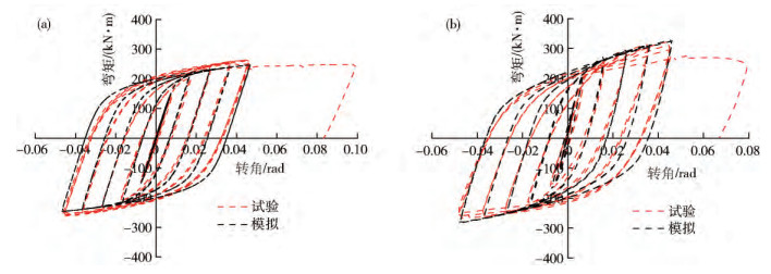
圖 4 滯回曲線對比.(a) ST-W/O; (b) ST-W
Figure 4. Comparison of hysteretic curves: (a) ST-W/O; (b) ST-W
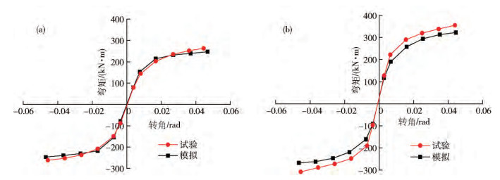
圖 5 骨架曲線對比.(a) ST-W/O; (b) ST-W
Figure 5. Comparison of skeleton curves: (a) ST-W/O; (b) ST-W
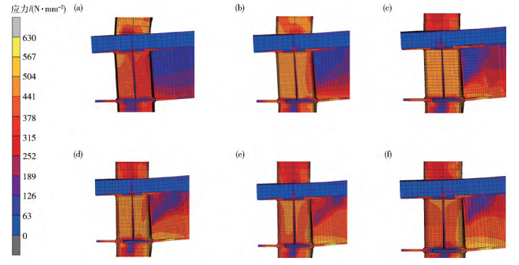
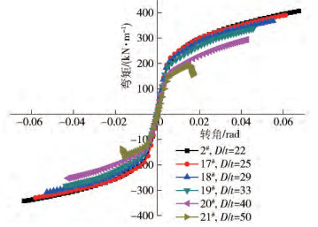
圖 11 不同寬厚比下節點域應力云圖.(a) D/t=50; (b) D/t=40; (c) D/t=33; (d) D/t=29; (e) D/t=25; (f) D/t=22
Figure 11. Effect of D/t on Von Mises stress of panel zone: (a) D/t=50; (b) D/t=40; (c) D/t=33; (d) D/t=29; (e) D/t=25; (f) D/t=22
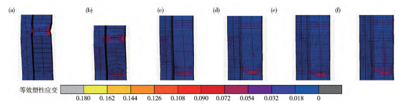
圖 12 不同寬厚比下節點域等效塑性應變圖.(a) D/t=50; (b) D/t=40; (c) D/t=33; (d) D/t=29; (e) D/t=25; (f) D/t=22
Figure 12. Effect of D/t on equivalent plastic strain of panel zone: (a) D/t=50; (b) D/t=40; (c) D/t=33; (d) D/t=29; (e) D/t=25; (f) D/t=22
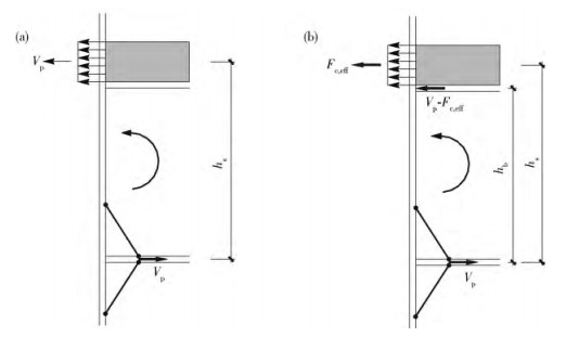
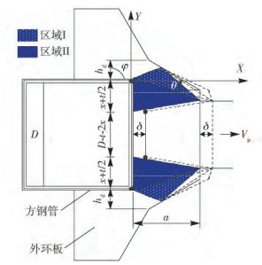
圖 13 計算簡化模型.(a) Vp≤Fc, eff; (b) Vp > Fc, eff
Figure 13. Analysis model: (a) Vp≤Fc, eff; (b) Vp > Fc, eff
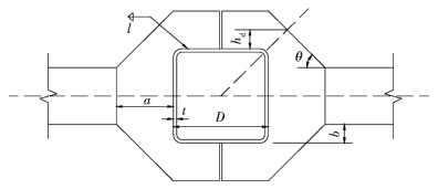
圖 15 外環板的梁柱連接節點的結構示意圖
Figure 15. Details of beam-to-column joint with external diaphragm
表 1 試驗和有限元的初期剛度、屈服點和塑性點對比
Table 1. Comparison of initial shear stiffness, yield moment, and plastic moment
試件編號 加載方向 初始剛度/(kN·m·rad-1) 屈服強度/(kN·m) 塑性強度/(kN·m) 試驗值 數值模擬 誤差/% 試驗值 數值模擬 誤差/% 試驗值 數值模擬 誤差/% ST-W/O 正向 20498 21202 3.43 170 175 2.94 209 224 7.18 負向 23653 21744 7.72 159 168 5.66 212 213 0.47 ST-W 正向 41737 43577 4.41 186 202 8.60 236 250 5.93 負向 24717 26024 5.29 167 183 9.58 216 232 7.41  下載: 導出CSV
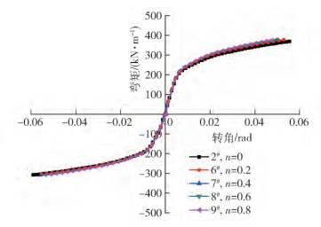
表 2 試件計算模型參數
Table 2. Details of parametric studies
模型編號 方鋼管/(mm × mm × mm) 梁/(mm × mm × mm × mm) 方鋼管柱寬,D/mm 軸壓比,n 樓板厚度,ts/mm 樓板強度等級 柱寬/厚比,D/t 1#(ST-W/O) 200×200×9 300×120×6×12 200 0 0 C40 22 2#(ST-W) 200×200×9 300×120×6×12 200 0 85 C40 22 3# 250×250×9 375×150×7.5×15 250 0 85 C40 22 4# 300×300×13.5 450×180×9×18 300 0 85 C40 22 5# 400×400×18 600×240×12×24 400 0 85 C40 22 6# 200×200×9 300×120×6×12 200 0.2 85 C40 22 7# 200×200×9 300×120×6×12 200 0.4 85 C40 22 8# 200×200×9 300×120×6×12 200 0.6 85 C40 22 9# 200×200×9 300×120×6×12 200 0.8 85 C40 22 10# 200×200×9 300×120×6×12 200 0 60 C40 22 11# 200×200×9 300×120×6×12 200 0 100 C40 22 12# 200×200×9 300×120×6×12 200 0 120 C40 22 13# 200×200×9 300×120×6×12 200 0 85 C20 22 14# 200×200×9 300×120×6×12 200 0 85 C30 22 15# 200×200×9 300×120×6×12 200 0 85 C60 22 16# 200×200×9 300×120×6×12 200 0 85 C80 22 17# 200×200×8 300×120×6×12 200 0 85 C40 25 18# 200×200×7 300×120×6×12 200 0 85 C40 29 19# 200×200×6 300×120×6×12 200 0 85 C40 33 20# 200×200×5 300×120×6×12 200 0 85 C40 40 21# 200×200×4 300×120×6×12 200 0 85 C40 50
下載: 導出CSV
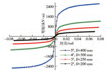
表 3 不同尺寸試件在性能點的梁端抗彎承載力
Table 3. Effect of specimen size on the moment-rotation behavior
試件編號 柱寬,D/mm 加載方向 K0FEM/(kN·rad-1) θyFEM/rad MyFEM/(kN·m) θpFEM/rad MpFEM/(kN·m) 5# 400 正向 336867 0.0049 1621 0.0090 1859 負向 197502 0.0060 1456 0.0095 -1732 4# 300 正向 141683 0.0055 671 0.0093 754 負向 87631 -0.0088 -609 0.0142 -675 3# 250 正向 82665 0.0064 387 0.0102 464 負向 49367 -0.0090 -355 -0.0151 -393 2# 200 正向 43577 0.0056 202 0.0097 250 負向 26024 -0.0090 -183 -0.0157 -216
下載: 導出CSV
表 4 不同尺寸下的單位截面抗彎系數梁端抗彎承載力的比值
Table 4. Effect of specimen size on M23, M24and M25
單位截面抗彎系數梁端抗彎承載力比值 正向荷載 負向荷載 屈服點 塑性點 屈服點 塑性點 M23 0.98 0.95 0.99 0.93 M24 0.98 0.89 0.99 0.93 M25 1.00 0.93 0.99 1.00
下載: 導出CSV
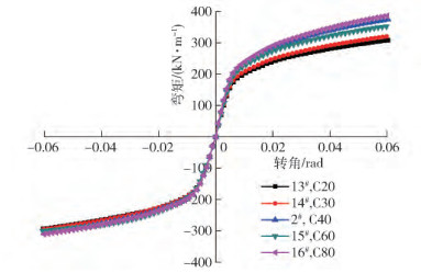
表 5 樓板強度等級
Table 5. Slab concrete strength
強度等級 立方體抗壓強度標準值,fcu, k/MPa 抗壓強度,fc/MPa C20 20 9.6 C30 30 14.3 C40 40 21.1 C60 60 23.1 C80 80 35.9
下載: 導出CSV
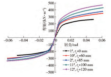
表 6 塑性點彎矩計算值與試驗值/有限元值對比
Table 6. Comparison of calculation results with experiment or FEM results
參數名稱 參數值 正向加載 負向加載 MpCAL/(kN·m) MpEXP或MpFEM/(kN·m) MpCAL/MpEXP或MpCAL/MpFEM MpCAL/(kN·m) MpEXP或MpFEM/(kN·m) MpCAL/MpEXP或MpCAL/MpFEM ST-W/O* — 198.1 209.0 0.95 198.1 212.0 0.93 ST-W** — 231.5 236.0 0.98 198.1 216.0 0.92 樓板厚度,ts/mm 60 216.9 224.5 0.97 198.1 186.6 1.06 85 231.4 236.0 0.98 198.1 216.0 0.92 100 236.6 266.0 0.89 198.1 199.8 0.99 120 243.4 287.0 0.85 198.1 203.2 0.97 樓板混凝土強度等級 C20 215.2 204.1 1.05 198.1 196.9 1.01 C30 223.8 220.0 1.02 198.1 196.6 1.01 C40 231.5 236.0 0.98 198.1 216.0 0.92 C60 231.5 264.5 0.87 198.1 199.0 1.00 C80 231.5 270.4 0.86 198.1 198.4 1.00 柱寬厚比,D/t 22 231.5 236.0 0.98 198.1 216.0 0.92 25 219.6 231.7 0.95 188 198.1 0.95 29 208.8 215.7 0.97 178.7 183.4 0.97 33 199.2 204.0 0.98 170.5 173.1 0.98 40 190.8 176.9 1.08 163.3 152.2 1.07 50 183.7 164.7 1.12 157.3 141.5 1.11 ??注: *和**為實驗.
下載: 導出CSV
259luxu-164<th id="5nh9l"></th> <strike id="5nh9l"></strike> <th id="5nh9l"><noframes id="5nh9l"><th id="5nh9l"></th> <strike id="5nh9l"></strike> <th id="5nh9l"><noframes id="5nh9l"> <th id="5nh9l"></th> <strike id="5nh9l"><noframes id="5nh9l"><span id="5nh9l"></span> <span id="5nh9l"><noframes id="5nh9l"><span id="5nh9l"></span> <strike id="5nh9l"><noframes id="5nh9l"><strike id="5nh9l"></strike> <span id="5nh9l"><noframes id="5nh9l"> <span id="5nh9l"><noframes id="5nh9l"> <span id="5nh9l"></span> <span id="5nh9l"><video id="5nh9l"></video></span> <th id="5nh9l"><noframes id="5nh9l"><th id="5nh9l"></th> -
參考文獻
[1] Miller D K. Lessons learned from the Northridge earthquake. Eng Struct, 1998, 20(4-6): 249 doi: 10.1016/S0141-0296(97)00031-X [2] Youssef N F G, Bonowitz D, Gross J L. A Survey of Steel Moment-Resisting Frame Buildings Affected by the 1994 Northridge Earthquake. Rep. No NISTIR-5625. Gaithersburg (Md): US National Institute of Standards and Technology, 1995 [3] Nakashima M, lnoue K, Tada M. Classification of damage to steel buildings observed in the 1995 Hyogoken-Nanbu earthquake. Eng Struct, 1998, 20(4-6): 271 doi: 10.1016/S0141-0296(97)00019-9 [4] Nie J G, Huang Y, Fan J S. Experimental study on load-bearing behavior of rectangular CFST frame considering composite action of floor slab. J Build Struct, 2011, 32(3): 99 https://www.cnki.com.cn/Article/CJFDTOTAL-JZJB201103016.htm聶建國, 黃遠, 樊健生. 考慮樓板組合作用的方鋼管混凝土組合框架受力性能試驗研究. 建筑結構學報, 2011, 32(3): 99 https://www.cnki.com.cn/Article/CJFDTOTAL-JZJB201103016.htm [5] Tao M X, Nie J G. Design methods of composite frame systems considering the slab spatial composite effect-Part Ⅰ: ultimate loading capacity. China Civil Eng J, 2012, 45(11): 39 https://www.cnki.com.cn/Article/CJFDTOTAL-TMGC201211006.htm陶慕軒, 聶建國. 考慮樓板空間組合作用的組合框架體系設計方法(Ⅰ) -極限承載能力. 土木工程學報, 2012, 45(11): 39 https://www.cnki.com.cn/Article/CJFDTOTAL-TMGC201211006.htm [6] Tao M X, Nie J G. Design guidelines of composite frame systems considering the slab spatial composite effect-Part Ⅱ: stiffness and verifications. China Civil Eng J, 2013, 46(2): 42 https://www.cnki.com.cn/Article/CJFDTOTAL-TMGC201302005.htm陶慕軒, 聶建國. 考慮樓板空間組合作用的組合框架體系設計方法(Ⅱ) -剛度及驗證. 土木工程學報, 2013, 46(2): 42 https://www.cnki.com.cn/Article/CJFDTOTAL-TMGC201302005.htm [7] Cheng C T, Chan C F, Chung L L. Seismic behavior of steel beams and CFT column moment-resisting connections with floor slabs. J Constr Steel Res, 2007, 63(11): 1479 doi: 10.1016/j.jcsr.2007.01.014 [8] Qian W W, Li W, Han L H, et al. Analytical behavior of concrete-encased concrete-filled steel tubular column to steel beam joints with RC slabs. Eng Mech, 2016, 33(Suppl): 95 https://www.cnki.com.cn/Article/CJFDTOTAL-GCLX2016S1018.htm錢煒武, 李威, 韓林海, 等. 帶樓板鋼管混凝土疊合柱-鋼梁節點抗震性能數值分析. 工程力學, 2016, 33(增刊): 95 https://www.cnki.com.cn/Article/CJFDTOTAL-GCLX2016S1018.htm [9] Liao F Y, Han L H, Tao Z. Behaviour of composite joints with concrete encased CFST columns under cyclic loading: Experiments. Eng Struct, 2014, 59: 745 doi: 10.1016/j.engstruct.2013.11.030 [10] Chen Y Y, Shen Z Y, Zhan C, et al. Three lines limit-analysis model for CHS K-Joints and its verification by tests. China Clivil Eng J, 1999, 32(6): 26 doi: 10.3321/j.issn:1000-131X.1999.06.004陳以一, 沈祖炎, 詹琛, 等. 直接匯交節點三重屈服線模型及試驗驗證. 土木工程學報, 1999, 32(6): 26 doi: 10.3321/j.issn:1000-131X.1999.06.004 [11] Tateyama E, Inoue K, Sugimoto S, et al. Study on ultimate bending strength and deformation capacity of H-shaped beam connected to RHS column with through diaphragms. J Struct Constr Eng, 1988, 389: 109立山英二, 井上一朗, 杉本正三. 通しダイヤフラム形式で角形鋼管柱に接合されるH形斷面はりの耐力と変形性能に関する研究. 日本建築學會構造系論文報告集. 1988, 389: 109 [12] Mansfield E H. Studies in collapse analysis of rigid-plastic plates with a square yield diagram//Proceeding of the Royal Society London. London, 1957: 311 [13] Mou B, Wang L L, Zhang C W, et al. Aseismic performance of beam-to-column joints with external-diaphragm considering the slab effect: experimental investigation. Eng Mech, 2018, 35(2): 160 https://www.cnki.com.cn/Article/CJFDTOTAL-GCLX201802020.htm牟犇, 王玲玲, 張春巍, 等. 考慮樓板影響的外環板式梁柱節點抗震性能: 試驗研究. 工程力學, 2018, 35(2): 160 https://www.cnki.com.cn/Article/CJFDTOTAL-GCLX201802020.htm [14] Jiang J J, Lu X Z, Ye L P. Finite Element Analysis of Concrete Structures. Beijing: Tsinghua University Press, 2005江見鯨, 陸新征, 葉列平. 混凝土結構有限元分析. 北京: 清華大學出版社, 2005 [15] Ministry of Housing and Urban-Rural Construction of the People's Republic of China, General Administration of Quality Supervision, Inspection and Quarantine of the People's Republic of China. GB50010-2010 Code for Design of Concrete Structures. Beijing: Standards Press of China, 2010中華人民共和國住房和城鄉建設部, 中華人民共和國國家質量監督檢驗檢疫總局. GB50010-2010混凝土結構設計規范. 北京: 中國標準出版社, 2010 [16] Mou B. Strength and Collapse Behavior of Offset Beam-to-Column Connection Panels with Exterior Diaphragms in Steel Structure and Concrete Filled Steel Tubular Structure[Dissertation]. Fukuoka: Kyushu University, 2015 -

 點擊查看大圖
計量
- 文章訪問數: 981
- HTML全文瀏覽量: 415
- PDF下載量: 26
- 被引次數: 0
